Understanding the fuse for the no idle function on International commercial trucks is essential for fleet efficiency and operational reliability. This technical guide provides a comprehensive examination of the fuse’s location, illuminates the fuse box’s intricate systems, and delves into the crucial role of engine control systems that facilitate the no idle feature. Each chapter builds upon the last, providing trucking company owners, fleet managers, procurement teams, and logistics experts with actionable insights to streamline truck performance and operational handling.
Tracing the No-Idle Fuse: A Practical, Integrated Walkthrough to Locate the Anti-Idle Circuit in International Commercial Trucks
Tracing the no-idle fuse in an International commercial truck is less about chasing a single labeled “no idle” slot and more about following the circuitry that governs engine management and idle control. In practice, the no-idle function lives behind the same protective hardware that guards the engine control system, the starter circuit, and the security features that keep the vehicle in a known, controlled state. This means that identifying the correct fuse or circuit protection device requires a careful, model-aware approach rather than a quick glance at a diagram labeled in plain language. The journey begins with locating the primary fuse box, but the path quickly broadens to involve service manuals, wiring schematics, and sometimes an appreciation for more modern protection modules that resemble circuit breakers more than traditional fuses. The goal is not simply to replace a blown part but to understand how the idle control signal travels from the power source, through protective devices, to the engine control module, and onward to the actuators that govern idle speed. Only then can a technician discern whether the fault lies in a blown fuse, a loose connection, a faulty relay, or an underlying ECM communication issue. In commercial trucking, where reliability intersects with safety and efficiency, this kind of diagnostic discipline matters as much as the mechanical repair itself.
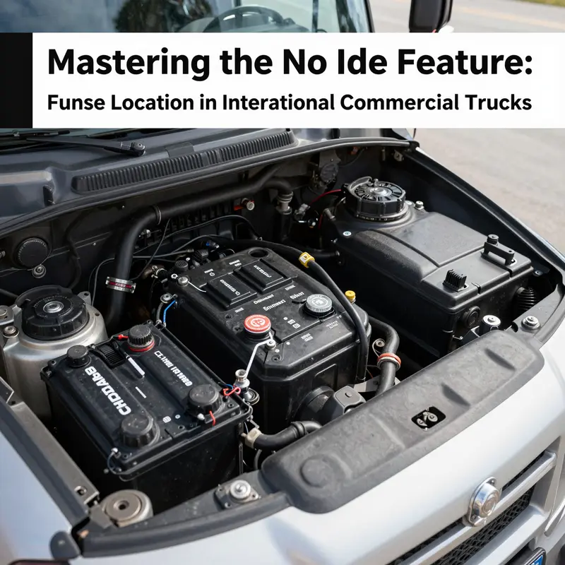
The primary fuse box in International trucks is typically located in one of a few conventional places, though modern configurations can scatter protection devices across more zones. A common scenario places the main fuse box under the dashboard on the driver’s side, where access is convenient for quick checks without crawling into the engine bay. Another frequent location is in the engine compartment, near the firewall or adjacent to the battery, where the harsh environment tests the robustness of every protective device. A third option, increasingly common in newer cabs, is a fuse or relay block tucked inside the cab, perhaps near the instrument cluster or beneath the center console. The exact arrangement varies with model year, engine family, and whether the truck leans toward traditional blade fuses or more advanced circuit protection assemblies. This variability underscores a fundamental point: the no-idle fuse may not be plainly labeled as such. It is more likely to be part of a cluster of fuses devoted to the engine control module, idle control circuits, ECM power, or immobilizer and security circuits.
Because fuse labeling and layout are model-specific, the most reliable way to identify the correct device is to consult the vehicle’s documentation and wiring diagrams that match the exact configuration of the truck in question. The owner’s manual often includes a fuse layout page with function labels like “Engine Control,” “Idle Control,” or “ECM Power.” If the manual is unavailable or its diagrams are ambiguous, the next best step is to access the service manual or a model-specific fuse box guide through authorized channels. In practice, technicians use VIN-based access to pull up wiring schematics that show how the idle control signal is energized and protected. This VIN-centric approach ensures the diagrams reflect the exact engine family, emissions equipment, and age of the truck, avoiding the confusion that comes from cross-referencing generic diagrams that may apply to other configurations.
When inspecting the fuse box, a careful, patient approach pays dividends. Always ensure the vehicle is fully powered down, the key is removed, and there is no risk of accidental cranking. A fuse puller or insulated tweezers is standard equipment for extracting suspected fuses. The visual check is simple: a blown fuse often shows a melted wire filament or a visible gap in the element. Yet some fuses may fail in a way that only a relay or a circuit protection module would reveal, leaving the fuse visually intact. In such cases, diagnostic clues come from the surrounding circuitry rather than the fuse itself. If the fuse is intact but the no-idle function remains absent, there is reason to suspect related wiring or a relay that governs the idle signal rather than the protection device. The safe practice is to replace any blown fuse with one of the exact amperage rating specified by the manual. A fuse rated higher than recommended can overlook a fault or risk electrical damage, while a fuse rated lower may blow again at idle attempts, masking the real problem.
Sometimes a truck uses a modern, resettable circuit protection module instead of a traditional fuse—an arrangement that resembles a small, colored block that pops out when a fault occurs. In these cases, the top button or a lever on the module can reset the device after addressing the root cause. The presence of such a module changes the immediate diagnostic workflow. A reset is only appropriate after confirming the underlying fault has been resolved; otherwise, the device will trip again, and the no-idle condition will persist. If a reset is performed but the idle issue returns, it is a signal to broaden the diagnostic net beyond the fuse box. Pathways to the idle control may involve the idle air control circuit, the communication link to the engine control module, or a related immobilizer component. In all of this, the technician’s task remains to verify the integrity of power supply lines, ground points, and connectors that feed the ECM and its idle control circuitry.
A robust diagnostic routine looks beyond the fuse itself. Loose connections, corroded terminals, and faulty relays can mimic a blown fuse by interrupting the idle control signal or ECM power. Corrosion, especially at battery grounds and at the shielding ground points near the firewall, can introduce resistance and intermittent faults that complicate idle behavior. Relays that feed the engine control module or idle actuator circuits can wear out or weld shut during cranking events, creating a condition where the idle control circuit does not receive a clean, stable command. In such scenarios, a simple fuse replacement does not address the root cause. The diagnostic path should incorporate a check of these components, followed by a scrutiny of wiring harness connectors that can become dislodged or stressed by engine vibration and thermal cycles.
In addition to the hardware checks, the diagnostic process often benefits from diagnostic tools that read fault codes and live data from the vehicle’s onboard computer. An OBD-II scanner can present codes tied to idle control or ECM communication, as well as sensor data that impacts idle performance. Corroborating the fault codes with physical checks of fuses, relays, and wiring creates a complete picture. The VIN-based wiring diagrams that are accessed through authorized service portals provide a schematic map for these checks. They help ensure that a technician follows the correct circuit paths and uses the appropriate amperage ratings for the specific truck configuration. This combination of documentation, safe practice, and hands-on inspection makes it possible to identify whether the no-idle issue originates from a blown fuse, a faulty relay, a degraded connector, or a deeper ECM fault.
The process, however, is not a one-size-fits-all procedure. The no-idle function is tied to anti-idling logic that can be integrated with various control strategies across different engine families and emission systems. The fuse that protects the idle control path may be grouped with the general engine-control protection circuitry rather than isolated in a single labeled “no idle” circuit. Consequently, model-year-specific diagrams—and the VIN-based access to those diagrams—become invaluable. When a technician updates the vehicle’s software or replaces components in the idle control chain, the electrical map of the truck can shift subtly. In those instances, re-checking fuse labeling and circuit protection locations with the latest service documentation helps ensure that the correct protection devices and control circuits are referenced during reassembly and diagnosis.
The practical upshot for maintenance personnel and truck operators is clear. Expect to spend time locating the correct fuse box, then navigate through the fuse map that labels functions rather than names. Be prepared for two realities: some trucks still rely on traditional fuses with clear function labels such as “Engine Control” or “ECM Power,” while others use compact circuit protection modules that require a reset procedure and a fault-addressing step before re-energizing the idle control circuit. In either case, the no-idle condition is a symptom that sits at the intersection of power delivery, control logic, and actuator function. The first principle remains simple: do not assume the problem lies solely in a single fuse. Confirm power presence at the ECM and idle-control pathways, verify ground continuity, and examine related relays and connectors. Only then should you move to a fuse replacement, following the exact amperage rating specified by the manual. In a fleet operation, standardizing this approach across trucks helps reduce downtime and keeps idle-related issues from drifting into more expensive repair territory.
For those who want to deepen their understanding or verify model-specific details, reliable, model-accurate documentation is essential. The International Truck Fuse Box Guide, available through official service portals and trusted repositories, provides diagrams that reflect the correct fuse mapping for each configuration. Access to accurate diagrams via VIN-based tools ensures that any intervention remains aligned with the truck’s unique electrical architecture. If a deeper dive is needed, the official service manuals harbor the complete schematics and the step-by-step procedural notes that accompany fuse testing, fuse replacement, and circuit protection inspection. With the right documentation, a technician can move from identification to corrective action with confidence, reducing the risk of inadvertently creating new electrical faults during repair.
Internal resource for ongoing maintenance practices can complement this technical workflow. For a broad overview of maintenance strategies and practical insights into how shops manage a diverse fleet, consider visiting the McGrath Trucks blog, which offers context-rich discussions that align with this topic and extend into related vehicle-care considerations. McGrath Trucks blog.
When the diagnostic path requires more than manual diagrams and personal expertise, the final step is to corroborate the findings with a trusted external reference. A model-specific fuse box guide and the associated wiring schematics from the official service resources provide the definitive validation. These resources help confirm that the fuse identified as “Engine Control” or “Idle Control” maps to the same circuit the idle-control strategy relies on. They also direct technicians to the correct test points and inspection sequences, ensuring the repair aligns with engineering intent and emission-compliance requirements. In practice, a technician might locate the relevant circuit on the fuse map, test the supply with a multimeter, inspect the downstream harness for signs of heat or damage, and then, if necessary, consult the service documentation to confirm the exact path the idle signal travels from the ECM to the idle-speed actuator or valve.
If the no-idle issue persists despite a correctly rated fuse replacement, or if the fuse appears to blow intermittently, the problem likely lies elsewhere in the control chain. A careful re-check of ground points can reveal subtle wiring issues that only show up under load. A degraded or sticky idle actuator can create a condition where the idle control circuit repeatedly demands more power, causing protective devices to trip or relays to fail in a way that mimics a blown fuse. In such cases, engaging diagnostic tools that read live ECM data becomes essential. The data may reveal an abnormal idle target or a mismatch between commanded idle and actual engine speed, pointing toward actuator faults, sensor faults, or software calibration issues rather than a power-protection problem. The guiding principle remains: fuse replacement without addressing the underlying idle control integrity is only a partial fix.
In sum, locating the fuse or protection device for the no-idle function in International commercial trucks requires a blend of systematic physical checks, model-specific documentation, and robust diagnostic testing. The fuse map is not a universal map; it is a model-and-year-specific guide that reflects the intricacies of modern engine management and anti-idling strategies. Operators and technicians who approach the task with a disciplined sequence—safety-first, location identification, diagram consultation, careful inspection, and targeted testing—stand a better chance of resolving no-idle symptoms with minimal downtime. The process not only restores idle control but reinforces the broader principle that effective electrical troubleshooting in heavy-duty vehicles hinges on precise documentation, cautious handling, and a willingness to probe beyond the obvious. For those who want to continue expanding their knowledge, the reference materials and official manuals provide the structured learning path. And for a broader sense of how this topic connects to fleet maintenance and industry trends, a visit to industry-focused resource hubs can offer additional perspectives on how idle-control strategies intersect with fuel efficiency, emissions compliance, and total cost of ownership over the life of a truck.
External reference: International Truck Fuse Box Guide – official service portal and manuals. https://www.internationaltrucks.com/service-support/manuals
Tracing the No-Idle Fuse: Unraveling the Hidden Circuit Behind Anti-Idling in International Commercial Trucks
The no-idle feature on international commercial trucks stands at the intersection of fleet efficiency, regulatory compliance, and driver comfort. It is a function designed to curb unnecessary engine idling, reduce fuel consumption, minimize emissions, and protect the battery and starter systems from wear during long wait times. Yet the fuse that controls or gates this no-idle capability rarely wears a label that reads “NO IDLE” in bold letters. Instead, it is embedded within a web of circuits inside the vehicle’s fuse box—the power distribution center that acts as the electrical nervous system for a modern heavy-duty truck. Understanding where this fuse resides, and how it is wired into the broader engine control architecture, requires a careful read of the vehicle’s service philosophy and a methodical diagnostic approach that can translate a generic “fuse box” into a precise, model-sensitive map of circuits. In practice, the search for the no-idle fuse becomes less about chasing a single component and more about tracing a path through the engine control module, the starter circuit, and the anti-theft or immobilizer subsystems that may interact with idle logic. This is not a one-size-fits-all hunt; it is a discipline of electrical schematics, nomenclature, and cross-brand variability that fleet technicians encounter across continents as they keep fleets moving through varied climates and terrains.
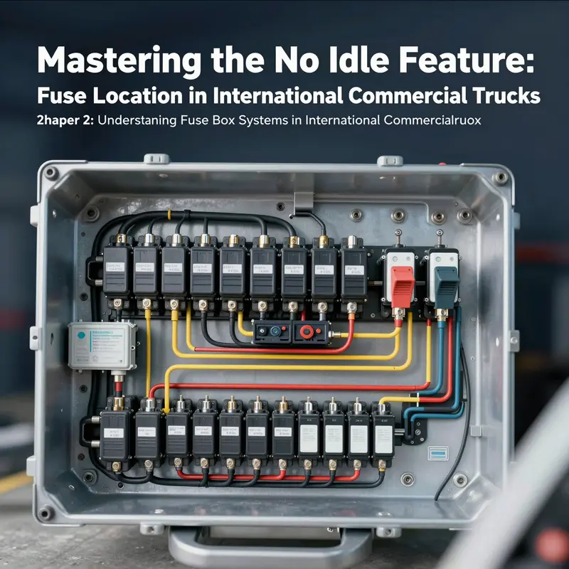
The fuse box in international trucks is designed as the central hub from which power is distributed to virtually every system that keeps the vehicle functional. It is engineered to protect circuits with fuses and circuit breakers that interrupt current flow when abnormal loads threaten wires or modules. In practice, that protective role is complemented by intelligent diagnostics that monitor current draw against expected baselines. Across the spectrum of international brands, the core purpose remains consistent: to isolate faults quickly, prevent cascading failures, and enable technicians to identify a culprit without dismantling the entire harness. Yet the physical arrangement, the density of fuses, and the labeling conventions can vary widely. Some boxes are compact, with a dense matrix of fuses arranged for high-load demands; others are modular, designed to ease maintenance by isolating subassemblies such as the engine controls, cabin electronics, or auxiliary systems. The design philosophy behind these differences mirrors the variables a fleet operator faces when choosing equipment for long-haul drayage, regional distribution, or hazardous-weather service in remote regions.
Within this landscape, locating the no-idle fuse requires a combination of practical steps and schematic literacy. The likely candidates are fused lines that feed the engine control module, the starter circuit, or the immobilizer system—three subsystems that can directly influence idle behavior either by sequencing engine start-stop logic, by enforcing safe shutdown in immobilized situations, or by interacting with anti-idle logic that governs when the engine can or cannot enter or sustain idle states. However, there is no universal “NO IDLE” fuse label that appears across all models and years. Instead, the no-idle control is often embedded as part of a more comprehensive control loop. It may reside on a circuit that shares power with the engine control module, or it may be tied into a relay that governs the primary ignition or fuel-supply relays. This means that an idling failure could surface not as a blown fuse for idle alone, but as an overcurrent event in a circuit that powers multiple engine and security functions. The consequence for the technician is a need to correlate fuse status with the behavior of the engine fault codes, the immobilizer status, and the rest of the electrical health indicators that the on-board diagnostic framework provides.
To approach this task with confidence, one must first locate the fuse box itself. In most trucks destined for international markets, the primary fuse box sits under the hood on the driver’s side, near the battery or toward the firewall. This placement makes it accessible to the technician while remaining protected from harsh road spray and debris. The cover of the fuse box typically bears a diagram or legend that identifies major circuits, but the exact labeling can be sparse for critical control lines that do not have a dedicated “NO IDLE” tag. It is here that the navigator’s eye must switch from reading plain labels to interpreting circuit groupings: engine control, ignition, starter, immobilizer, and power to the ECM. The goal is to locate the fuse or the fuse block that supplies current to the engine control network and, specifically, to the elements of idle logic. In practice, a technician will confirm the physical location of the fuse box, then compare the diagram under the cover with the actual wiring harness routing within the engine bay. When a diagram is absent or obscure, the VIN becomes the navigator’s key. By entering the vehicle’s VIN into an authorized diagnostic portal or service tool, technicians can pull model- and year-specific wiring schematics that reveal the exact fuse assignments for that truck’s configuration.
Accessible, VIN-specific diagrams are indispensable because they account for the differences that inevitably arise from regional variations, engine families, emission controls, and electrical harness options. A no-idle feature might be implemented through an engine control module that enforces a minimum runtime for certain operational conditions, or through anti-idle software that engages upon detected battery discharge or thermal thresholds. In some configurations, an immobilizer or security feature can complicate idle behavior by restricting engine start until a valid authentication sequence completes. When the no-idle function depends on such a security layer, the fuse controlling this power circuit may also tie into the immobilizer control, making the diagnostic process more intricate. This interconnectedness underscores why the no-idle fuse, while conceptually simple as a protective device, often requires circuit-level insight rather than a quick visual inspection.
For technicians and fleet managers seeking practical, model-aware guidance, a trusted route is to consult a dedicated fuse box guide that maps out the distribution center’s layouts across different makes and regional offerings. These guides compile schematics and fuse-by-fuse descriptions that help isolate the anti-idle control circuits within broader engine and security networks. A well-curated guide can save hours of tracing wires and confirm whether the suspected no-idle circuit is a distinct fuse, a shared feed, or a relay-controlled path. The overarching pattern is clear: no single fuse label will universally identify the no-idle function. Instead, the correct identification rests on recognizing whose power is feeding the engine control module, the starter relay, and the immobilizer subsystem—and then confirming how those feeds interact with idle logic via the vehicle’s diagnostic data stream.
In the field, these diagnostic principles translate into a practical workflow. First, locate the fuse box and inspect the cover diagram for the major circuits tied to engine control and ignition. Second, verify whether a fuse is blown by removing it and inspecting its continuity or by using a digital multimeter on its circuit. Third, cross-check the labeled circuit against the vehicle’s wiring harness and, if available, the factory diagrams that accompany service manuals. Fourth, if a fuse appears intact but idle behavior remains abnormal, widen the check to the related relays, fuses in adjacent banks, and the wiring harness that runs from the fuse box to the ECM and to the immobilizer module. Finally, if the no-idle fault persists, pull the vehicle’s diagnostic trouble codes. The codes can reveal whether the root cause lies in a power feed, a sensor input, or an interlock condition between the immobilizer and the engine control logic. This stepwise, evidence-based approach reduces guesswork and protects against misidentifying a symptom as the root cause.
The literature on fuse box design across international fleets illuminates how different brands have solved the same problem with varying degrees of modularity and monitoring sophistication. In many cases, the fuse box is not merely a passive block of fuses. It is a platform that integrates sensors, self-diagnostics, and sometimes smart monitoring that can alert the technician to abnormal current consumption or a failing circuit before a fuse actually blows. Some families of trucks adopt ruggedized, sealed enclosures with expanded fuse banks to handle heavy electrical loads associated with sophisticated cabin electronics, advanced lighting, and auxiliary systems. Others emphasize modularity, enabling a rapid swap of entire subassemblies if the no-idle control logic proves stubborn or if the engine control network requires a clean start point after repeated idling shutdowns on the road. This evolution—from simple fuses to intelligent, modular power centers—reflects the larger trend of reliability engineering in international trucking, where downtime hurts throughput and where predictive maintenance can save substantial operating costs for fleets that cross borders and climate zones.
The no-idle fuse search, then, becomes a narrative about circuit literacy and the art of reading electrical topology rather than a single, static location. It is also a reminder that, in a cross-border fleet, a mechanic must be prepared for variation in fuse labeling, wiring architecture, and the interplay between engine management and security systems. To support a robust diagnostic process, technicians often rely on an amalgam of sources: the official service information portal for the truck line, the VIN-specific wiring diagrams, and the practical wisdom shared in maintenance communities and technical blogs. A representative maintenance mindset favors cross-checking across these sources, rather than trusting a single diagram found on a shop wall. The result is a diagnosis that respects both the universality of engine control concepts and the local specificity of a given vehicle’s electrical backbone.
From the ground, no-idle protection is not merely a computer instruction tucked inside a box. It is a set of decisions embedded in the electrical architecture that seeks to enforce efficient operation while preserving safety and reliability. The fuse that ultimately gates idling is part of a larger conversation about how modern trucks balance energy management, engine health, and regulatory constraints across regions with divergent emission standards and fuel quality. In fleet operations, this translates into expectations about serviceability: technicians need quick access to accurate schematics, fast fault isolation, and reliable sources of model-specific information. The practical take-away is straightforward. When approaching the no-idle circuit, treat the fuse box as the gateway to understanding idle behavior. Begin with the obvious, confirm the core engine control and ignition circuits, then expand the search to the immobilizer and any security-linked feeds. If the fuse is intact and the idle remains constrained, consider the possibility that the issue lies not in a blown fuse, but in an idle strategy that has been overridden by software, a sensor fault within the engine control loop, or an abnormal power draw from ancillary systems that clamps the available current for idle control.
For readers who want hands-on context beyond the theory, practical hands-on resources exist that distill these concepts into field-tested guidance. A respected repository of electrical schematics and troubleshooting practices can be found in a dedicated industry resource that curates model-specific fuse diagrams and wiring information. Within the broader maintenance ecosystem, you will often find communities and manuals that speak in the language of fuses, relays, and controllers. To deepen practical understanding and stay connected with fleet-maintenance perspectives, you can explore insights from the broader trucking community at McGrath Trucks blog. This resource gathers real-world notes on maintenance, repair scheduling, and common electrical challenges that fleets encounter on the road. The emphasis across such writings is to translate page-level diagrams into a working map that a technician can carry to the shop, to the yard, or into the field where idling management begins its daily test.
In sum, the quest to locate and verify the no-idle fuse is less about finding a singular, universal label and more about building a circuit-aware mindset. It requires a grasp of how the engine control module, ignition path, and immobilizer interfaces are wired in a given model-year configuration, plus access to VIN-specific wiring diagrams that map those circuits to an actual fuse bank. The fuse box remains the physical gateway, but the true map is in the schematics that describe how power flows from the battery into the heart of the engine management system, how relays control when the engine may start or idle, and how immobilizer logic interacts with the idle strategy to protect the vehicle and the fleet. As vehicles evolve and as fleets push deeper into global operations—where different climates, fuels, and regulatory regimes intersect—the no-idle fuse becomes a symbol of this broader engineering philosophy. It is the reminder that, in international trucking, simple objectives like saving fuel and reducing wear hinge on a complex, carefully engineered electrical backbone that must be understood, navigated, and maintained with precision.
External resource: https://www.alibaba.com/product-detail/A-Complete-Guide-to-Heavy-Truck-Fuse-Box_1600489785372.html
The Electrical Brain Behind No Idle: Tracing Fuses, ECUs, and the Quiet Shutdown That Saves Fuel

Across the modern heavy vehicle landscape, the No Idle feature stands as a quiet guardian of efficiency. It is not a single switch you flip on the dashboard but a tightly choreographed interaction among power, perception, and control. The fuse that powers this capability sits in the same general neighborhood as every other critical circuit: inside the fuse box, the junction box, or the power distribution center tucked under the hood on the driver’s side. The precise fuse that makes No Idle possible, however, rarely wears a placard that says “No Idle.” Instead, it belongs to a family of circuits feeding the engine control architecture—circuits that connect the engine control module, the starter, and the immobilizer into a single, responsive system. Identifying the exact fuse is less about a label and more about reading the map that the vehicle’s service documentation provides. In practice, the path to the No Idle fuse begins with the same careful steps a technician uses to diagnose any complex electrical system: consult the fuse box guide specific to the model year, confirm the vehicle identification number (VIN) to access wired schematics, and acknowledge that the No Idle function is embedded in the engine’s nervous system rather than sitting as a standalone, easily labeled feature.
The fuse box itself is a compact citadel of circuits. Within its plastic walls lie banks of fuses and relays that empower the ECM, control the starter circuit, and protect the immobilizer network. When No Idle is enabled, the ECU—commonly referred to as the engine control module in broader circles—pulls in data from a constellation of sensors, then signals the actuators that govern the engine’s behavior. The No Idle logic relies on a delicate balance: the engine must be allowed to shut down during true idle while ensuring a swift and reliable restart when the driver returns to operation. The fuse that supports this logic is not a single, outward-facing toggle; it is the linchpin that feeds the ECM’s power, but the ECM itself is the conductor that coordinates the elements needed to execute shutdown and restart sequences.
This arrangement becomes clearest when we consider the real-time inputs that guide the ECU. The Mass Air Flow sensor, for example, feeds data about air intake that correlates with engine load. The Throttle Position sensor informs the ECU about how far the accelerator pedal has moved. The RPM sensor and the crankshaft angular position sensor give the ECU a precise sense of engine speed and position. The Exhaust Gas Oxygen sensor reveals combustion quality. Taken together, these inputs allow the ECU to answer a fundamental question: is the engine at a genuine stop, or is it merely idling with minimal load? If the data indicate a stop state—say the vehicle is at a full stop, the brake is released, and the accelerator is not engaged—the ECU can initiate a carefully timed shutdown sequence. That sequence is designed not to surprise the operator or compromise safety; it is calibrated to ensure a smooth restart should the vehicle resume movement.
The control logic that choreographs No Idle sits inside the software that runs on the embedded processor at the heart of the ECU. It is not a blunt on/off mechanism. Instead, it is a series of decisions and safeguards designed to harmonize fuel economy with reliability. The idle control valve, throttle-body fuel injectors, and spark delivery are all regulated by the ECU as part of the shutdown and restart protocol. The challenge is to suppress unnecessary engine activity while preserving essential systems such as climate control, hydraulics, and safety circuits. In practice, the engine may be allowed to shut down when it is safe to do so, but the cabin’s temperature, battery state, and the status of auxiliary devices are continuously assessed to ensure that the operator’s comfort and safety are not compromised when the motor restarts.
This is where the fuse and the ECU converge in daily operation. If the No Idle fuse fails, the engine control system loses a corridor of power that can affect the ECM’s ability to regulate these sequences. The consequence is not merely a stalled opportunity to save fuel; it is a potential misalignment between perception and response. The vehicle can end up relying on a default idle strategy that is less efficient, or worse, it may fail to restart promptly when the driver expects it to. That is why technicians emphasize the importance of checking not just the label on a fuse but the entire circuit that supports the ECM’s power supply, ignition circuits, and immobilizer circuits. In many cases, the precise fuse that governs No Idle is identified through model-year–specific wiring diagrams and service manuals rather than through a generic guide. The VIN acts like a key that unlocks a tailored schematic, showing which branch of the power distribution network is responsible for the anti-idling functionality. This approach reflects a broader truth about modern trucks: electrical systems are highly individualized, and a one-size-fits-all map is rarely sufficient for precise diagnostics.
The practical steps to navigate this landscape are often straightforward, yet they demand patience and discipline. Start with the fuse box guide that corresponds to the truck’s configuration. Confirm the engine type and year, since even small revisions in the electrical architecture can shift fuse designations. Then, use the VIN to pull a wiring schematic that reveals how the No Idle circuit is wired into the ECM, the immobilizer, and the starter circuit. In many workshops, technicians rely on diagnostic tools that access the vehicle’s onboard memory, listing active faults and live data streams that illuminate how the No Idle pathway behaves during a test drive. The goal is not merely to identify a blown fuse; it is to understand whether the No Idle function is being correctly enabled, whether the ignition sequence remains intact, and whether the immobilizer thread remains secure while the engine is shut down.
The No Idle feature also carries implications beyond the cab and the immediate powertrain. In marine and mixed-operational settings, similar logic governs how engines, generators, and auxiliary systems behave during stationary periods. A vessel’s energy management system, for instance, may monitor flow meters and other sensors to determine whether idling is justified or if power can be reallocated elsewhere while still maintaining essential services. In such contexts, the ECU and its allied control circuitry operate as a distributed nervous system that links propulsion, power generation, and environmental controls. The scale and complexity may differ, but the design principle remains the same: data from real-time sensors feeds a central decision-maker that orchestrates shut down and restart to optimize efficiency without compromising readiness.
To appreciate the No Idle architecture fully, it helps to consider the kinds of safeguards embedded in the system. The software that governs the ECM is designed to prevent abrupt shutdowns that could damage the engine or upset the electrical network. Timers, interrupt control units, and dedicated logic paths ensure that the transition into no-idle mode occurs only under safe conditions and that a restart is ready to occur at the driver’s command. The embedded processor serves as the brain, but it relies on a network of supporting hardware that ensures reliability under challenging operating conditions—vibrations, temperature swings, and the demanding electrical loads of modern day cab interiors. The general principle applies across heavy trucks and larger vehicles: an intelligent system that can monitor, decide, and execute with a built-in tolerance for irregularities and interruptions.
The narrative of No Idle is not confined to on-road operation. Marine applications illuminate the same core ideas in a different environment. There, the concept of energy efficiency intersects with real-time monitoring across multiple machines—main engines, diesel generators, and boilers. The IoT layer that collects data—flow rates, energy demand, and voyage history—feeds an energy-management model that can automate shutdowns during idle periods while preserving the ability to restore power when needed. In this broader view, the No Idle idea becomes a prototype for how modern machines manage power intelligently. It demonstrates how an electrical system, when properly wired and correctly governed by software, can shave fuel use, reduce emissions, and extend machine life without sacrificing reliability or safety. That synthesis—power, perception, and performance—begins with the fuse and ends in a design that treats the engine as a dynamic, adaptable system rather than a simple motor that either runs or stops.
Within this framework, the role of the fuse box is not merely to supply juice; it is to define the boundaries within which the No Idle logic can operate. If the fuse is underpowered or compromised, the ECM loses access to essential signals and power pathways. If the immobilizer circuit is unstable, it may prevent a restart or create security-related delays. If the starter circuit cannot receive clean power, the engine cannot be restarted promptly when the driver wants to resume movement. In each case, the elegance of the No Idle concept is tested by the reliability of its electrical backbone. The fuse box, then, becomes a quiet sentinel—one that must be correctly understood and maintained if the No Idle feature is to deliver its promised benefits.
The practical takeaway for operators and technicians is simple in spirit but nuanced in execution. The No Idle function hinges on a correctly functioning power path to the engine control architecture, a path that is secured by a well-documented fuse map and a VIN-specific wiring diagram. Regular checks should extend beyond replacing a blown fuse to verifying that the overall power distribution around the ECM remains stable during start-stop cycles and that no parasitic drains are pulling power away from critical circuits when the engine is shut down. It is equally important to recognize that the No Idle feature does not exist in isolation. It is part of a broader ecosystem of engine management, climate control, battery health, and safety interlocks. When the ecosystem is coherent, the engine can be retired from idle with grace, cars and cab interiors stay comfortable, and operators gain meaningful improvements in fuel economy and emissions.
For readers who want a broader, human context, a gateway to industry discussions on electrical systems and maintenance practices can be found in the industry blog that continually aggregates practical insights for fleet operators and technicians. This repository of practical knowledge provides a complementary perspective to the more technical manuals and wiring diagrams, grounding the No Idle discussion in real-world decisions and day-to-day workflows. See the McGrath Trucks blog for a concise overview of how electrical systems influence maintenance and performance in the field.
External resources can offer deeper dives into the engine control concepts that underpin No Idle. The engineering literature, technical handbooks, and service-oriented articles explore how embedded processors, timers, and interrupt control units coordinate to produce reliable shutdown and restart sequences. Researchers describe the central nervous system nature of the engine control unit, how it integrates diverse sensor streams, and how software logic translates raw signals into controlled, low-emission operation. For a more technical treatment of engine control concepts and their theoretical underpinnings, readers can consult external educational materials and engineering summaries that discuss engine control units and their role in modern powertrains. These sources provide a scholarly complement to the practical, service-oriented guidance embedded in operator manuals and diagnostic tools.
In sum, the No Idle feature emerges as a confluence of mechanical design and digital intelligence. Its success rests on a robust electrical backbone—the fuse box and the circuits feeding the ECM—paired with a sophisticated control algorithm that interprets sensor data and translates it into precise mechanical actions. The result is a system that can reduce fuel burn and emissions without sacrificing safety or reliability. The fuse may be small, but its impact reaches through the entire powertrain, influencing how and when the engine chooses to sleep and how quickly it wakes when the driver returns. This quiet, almost invisible orchestration—between fuse, ECU, sensors, and actuators—defines the modern No Idle capability on international commercial trucks and echoes in marine and industrial contexts where energy discipline is equally valuable. The fusion of electrical protection, control logic, and real-world restraint is what keeps the No Idle feature trustworthy, predictable, and truly useful in the daily rhythm of highway and harbor alike.
External resource: https://www.sciencedirect.com/topics/engineering/engine-control-unit
Final thoughts
Navigating the complexities of the no idle function on International commercial trucks is critical for maintaining operational efficiency and compliance. The verification of fuse locations and understanding the fuse box systems not only aids in troubleshooting but also reinforces the integrity of fleet management practices. By combining knowledge of the fuse system with insights into engine control technology, fleet operators can enhance vehicle performance and minimize downtime. A meticulous approach towards understanding these mechanisms can provide subtle yet significant advantages in day-to-day operations.